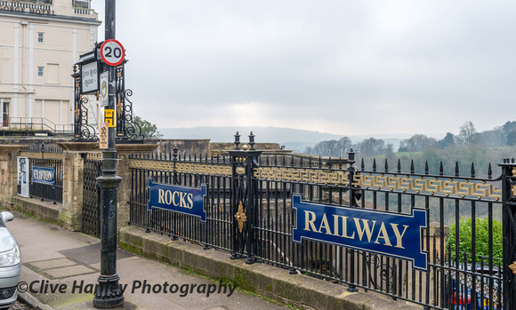
Sadly this funicular Railway was shut down in 1934
Behind the entrance is a tunnel cut through the rock which extends at a steep angle to emerge in the now derelict small triangle of ground between the junction of Princes Lane and Sion Hill, adjacent to the Avon Gorge Hotel. Within this triangle of ground is the upper Station which has long since fallen into a state of disrepair. The tunnel itself forms a straight and direct connection between the upper and lower stations. A Description Of The Original Railway. The tunnel is 500 feet long, semi elliptical in cross section with a roof height of 18 feet and a width of 27 feet 6 inches it climbs a vertical distance of 240 feet on a rising gradient of about 1:2.2, that is a vertical rise of 1 foot for every 2.2 feet of forward travel. The tunnel was blasted and cut through badly faulted limestone and was brick lined in almost its entirety with a wall thickness of 2 feet
Although the tunnel was lit by daylight at both top and bottom, this was supplemented by gas lamps installed down the tunnel length. From the surface, the upper station appears to be a small single storey building, triangular in plan, with a facade of ashlar bath stone faced masonry construction facing Princes Lane and the Avon Gorge. The Sion Hill elevation consisted of iron railings between masonry piers: the railings are now covered with sheets of boarding. There are two entrances to the upper station, one at the junction of Princes Lane and Sion Hill, the other onto Sion Hill itself. The Sion Hill entrance had an ornamental iron arch over. A visitor would descend down steps from either entrance to the top station into a small platform which was below upper street level. In fact the platform extends under the pavement in Sion Hill, and a series of small arched roof vaults between the rock face and a substantial steel beam, itself supported on cast iron columns, support the pavement of the street above. The remainder of the 15 feet wide platform which is not recessed under the pavement was covered with an awning of small glass panels set in iron frames (pavement lights) forming a floor on which sightseers could stand and take in the view, or watch the cars ascending and descending the tunnel. Most of these glass panels are still in place, but the grid of supporting steelwork in which they are mounted is in poor condition. At the head of the tunnel was a timber screen, pay box and turnstiles, together with the two large pulley wheels described later.
The lower station itself is constructed inside the rock, and was finished with the facade erected flush with the rock face. This facade was of rubble construction using grey pennant stone, locally mined and used extensively in the less expensive houses being built in Bristol in the 1800's. Quoins and architraves were of bath stone with three decorative gargoyles above the three entrance arches, the two windows, one on either side remaining undecorated. A verandah was originally incorporated but was later removed, the six smaller arches of the upper floor being retained as picture windows giving a superb view across the river, with a tiled timber canopy above to provide shade. The building behind this facade was of two storeys and the ground floor consisted of two rooms. One contained the turnstiles and pay box (now removed) set in a floor of red 6 inch tiles. The walls of this room were lined from floor to ceiling with vertical pine matchboarding. The other room was undecorated and contained the pumping machinery. On the second floor was situated a small toilet installed in September, 1894 and some staff facilities. A later addition above the entrance portals were three bath stone lintels with the legend 'Clifton Rocks Railway' carved in stone.
From the day that it opened the line was operated by four cars. Each car consisted of an upper passenger section, with a triangular chassis angled to suit the gradient of the tunnel. The upper passenger section resembled in appearence the horse-drawn tramcars to be found operating during the 1890s on the City tramway, and are believed to have been constructed in Birmingham by Starbruck who built tramcars for the City. Each car could accommodate 18 seated passengers and had sliding doors at either end, the door at the end facing the river opening onto a small platform on which the 'brakesman' or attendant rode alongside the brake control. Cars were painted light blue and white with gold lining when new, but were later re-painted in colours similar to the Bristol Tramway Company. The cars were mounted by four leaf springs onto the chassis which were built by Messrs Gimsons of Leicester. These four chassis were part of a batch of six ordered on 7 March 1892 and delivered in December, 1892. The balance of the order was for the Bridgenorth/Castle-Hill Railway, those for the Clifton Rocks being designated by a C prefix on the detail drawing. The Bridgenorth equipment had a wider guage at 3 ft 8 ins. The chassis were constructed of 8 in by 3 in steel channel section 14 ft 6 in long, carried on four wheels. The only item not manufactured at Leicester within the chassis were the axles which were supplied by J.H. Lloyd and Co. The axles ran in brass bearings fitted onto cast iron housings bolted onto the top side of the bottom chassis member. The cars were handed left and right.
Cars ran in pairs on adjacent tracks of 75-80 lbs/yd flat bottom rail. These rails were bolted directly onto concrete cross sleepers the width of the tunnel at 5 feet spacing firmly bedded in the rock bed of the tunnel, The gauge of the railway was 3 feet and each pair of tracks either side of the tunnel were at 5 feet 6 inch centres.
Each pair of carriages was connected together via two steel wire cables 'being 30 times stronger than the load that has to be put upon them' which turned around large pulley wheels at the top of the tunnel. The principle behind the operation of the cars is known as 'water balance'. As one car ran down its rail its companion car would be pulled up, the weight of the water plus passengers in the descending car overbalancing the weight of the passengers in the ascending car. Mounted in the frames beneath each passenger section was a tank of 12 gauge steel bolted on 3 inch x 1.5 inch rolled steel joists and fitted with a lid of 18 gauge steel. At the beginning of a journey, releasing the brakes on both cars allowed the top car to descend, pulling the bottom car up in doing so. Equipped with all quot;mod consquot;, an electric telegraph manufactured by King, Mendham amp; Co. of Bristol, permitted the brakesman of the car at the bottom to inform his opposite number in the car at the top of the number of passengers to be raised. By this means, the correct weight of water required to balance the load could be added to the top car. If the ascending car was empty, then the weight of passengers in the descending car (if full) was sufficient to activate the system without the water tank being filled. Upon completion of the journey and whilst the passengers disembarked, water in the tank of the car at the base of the incline was automatically emptied into a sump before being pumped back up to a reservoir at the head of the incline by duplicate sets of pumps powered by self starting quot;Otto cyclequot; gas engines manufactured by Crossley of Manchester. The water which was employed to operate the line was therefore used over and over again, the cost of the motive power for working that required to drive the gas engines for pumping the water.
The design of the system showed a great concern for safety: some might describe the design as 'belt, braces, piece of string and the Royal Air Force'. This is amply demonstrated in the superb braking systems which were arranged 'such as to satisfy the requirements of the most nervous of passengers'. Duplicate brakes were incorporated, operated by hydraulic pressure and acting on both sides of the rails of the line. Another set of duplicate brakes were incorporated for arresting the speed should the cars for any undue cause exceed their proper pace and a third set of duplicate brakes were also incorporated for automatically stopping the cars should either of the other two systems fail, or should the two steel ropes break at the same time.
The hydraulic brakes acting upon the rails were the ones controlled by the brakesmen. They were designed such that the brakesmen had to give their attention to prevent the car from stopping, rather than trying to make the car stop. Thus, should one brakesman become careless or lose his hold of the brake windlass handle, both of the cars would immediately stop, even though the brakesman upon one of them might be unaware of the problems which had befallen his companion, The hydraulic brake mechanism consisted of hydraulic rams acting into cast iron blocks which gripped the rails in a 'callipe' action. The rams were connected by copper tubes to much larger master cylinders, the hydraulic fluid being water. Pressure on the system was applied by heavy weights acting on the top of pistons in the master cylinders. The weights were directly connected to the conductor's windlass hand wheel. The act of turning the windlass hand wheel would raise the weight from the top of the master cylinder reducing the pressure in the system and hence the grip of the cast iron blocks on the rails. Should either conductor release his hold on the handle for any reason, the weights would automatically drop back under gravity, increasing the pressure in the system, applying the brakes and bringing both cars to a halt.
The speed governing brake acted independently of the controlling brake to cause the hydraulic pressure to be increased and the rails to be gripped should the recommended speed be exceeded. How it worked is not clear, but from the general specification it appears to have been operated by means of an eccentric on the lower axle. The third system of brakes which would operate in th